

Assembly videos
Getting started
Open your ULIO 3D printer kit, layout all the parts on a flat table and sort the fasteners into small separate containers
In this section you will need to purchase beforehand the following items:
Lubricant: Good quality sewing machine oil meaning non-staining and non-gumming or regular Vaseline
Adult supervision and assistance are required
Begin the assembly
Estimated time: 8 hours
A
cleaning and Sanding
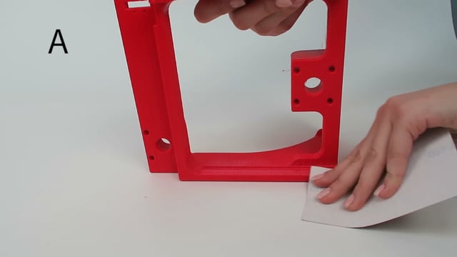
Clean excess plastic strings within the teeth of the racks, pinions, railings and all openings
All moving parts should slide with ease before assembly, else go back to our STL download page for solutions
B
preparing the gears
Verify if the X, Y and Z gears fit tight onto the motor shaft
If the bore is too small manually drill out a 5 mm hole
c
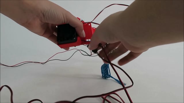
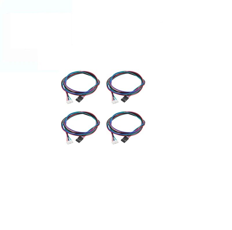
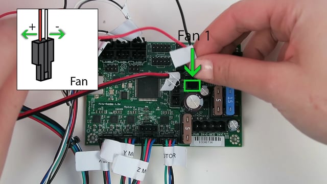
WIRE TagGing
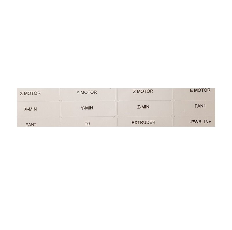
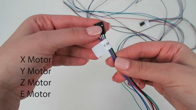
FAN2 and the thermistor T0 have similar wiring connectors
FAN1 tag is not shown in the video
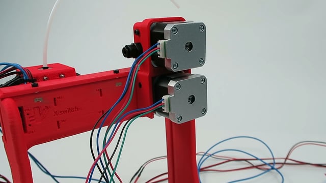
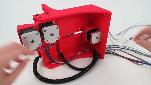
d
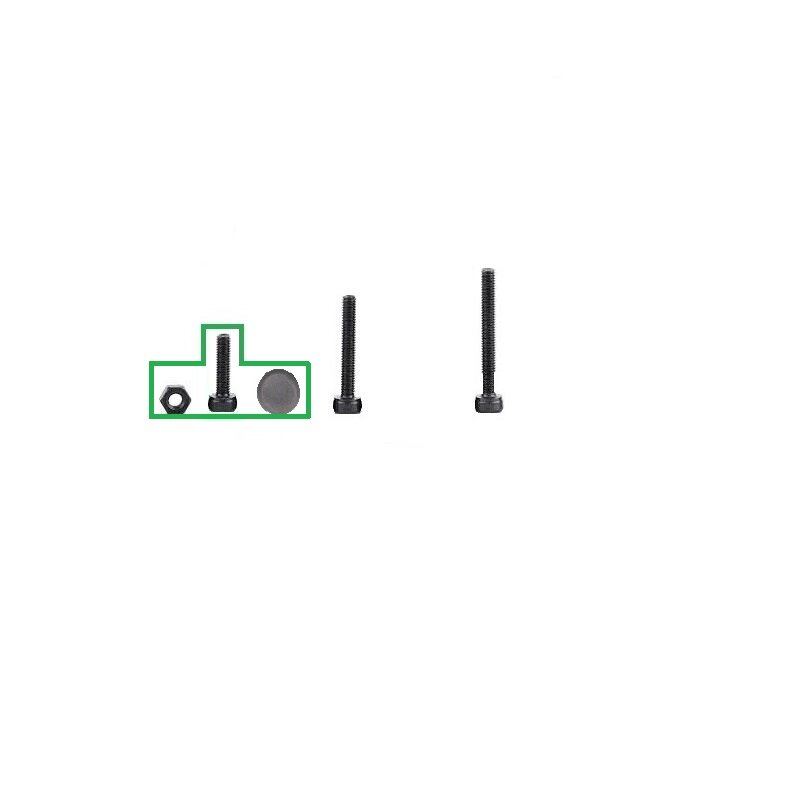
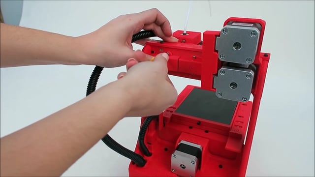
X axis motor

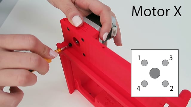
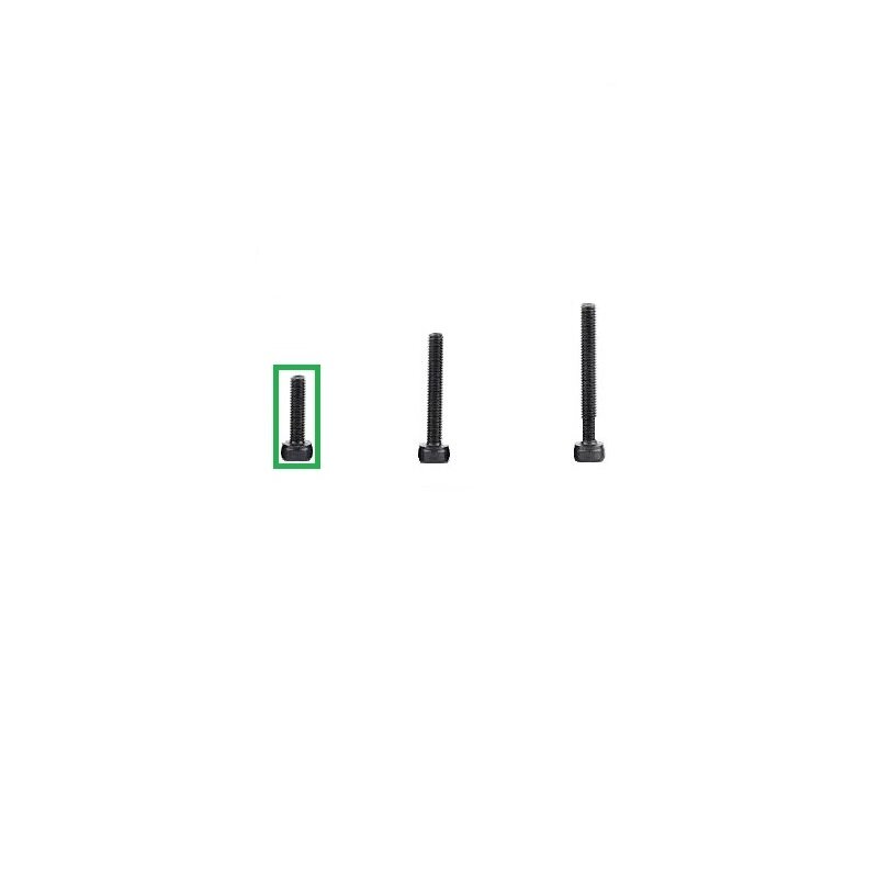
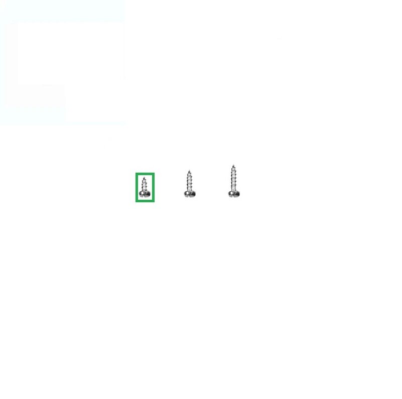
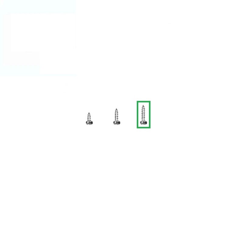
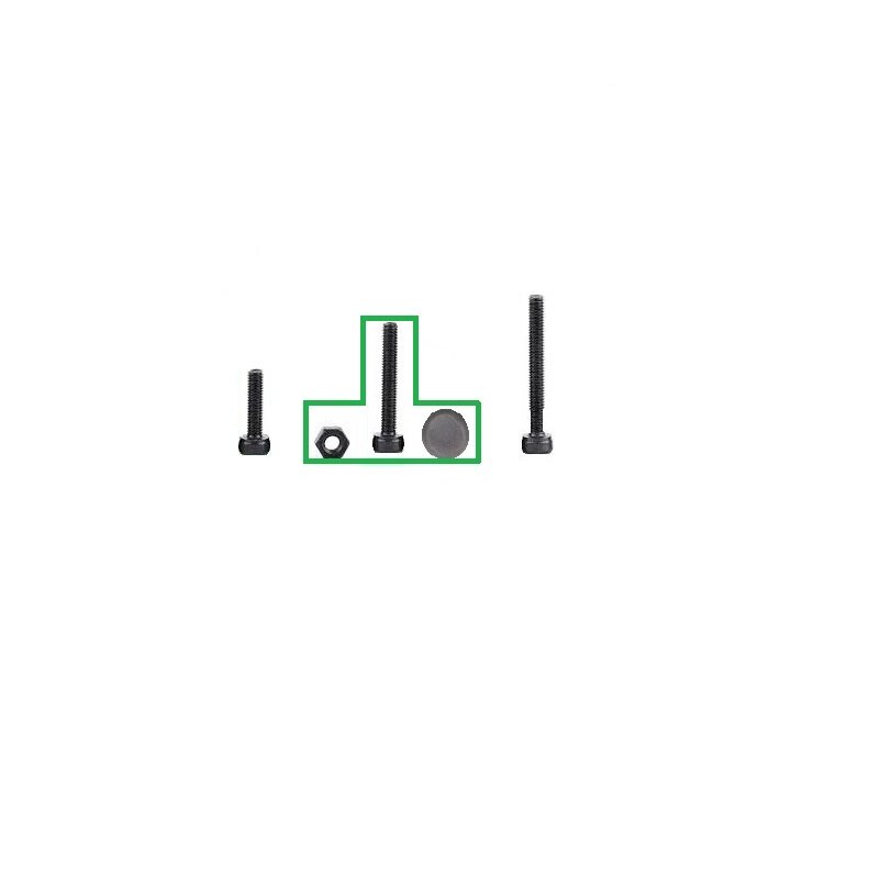
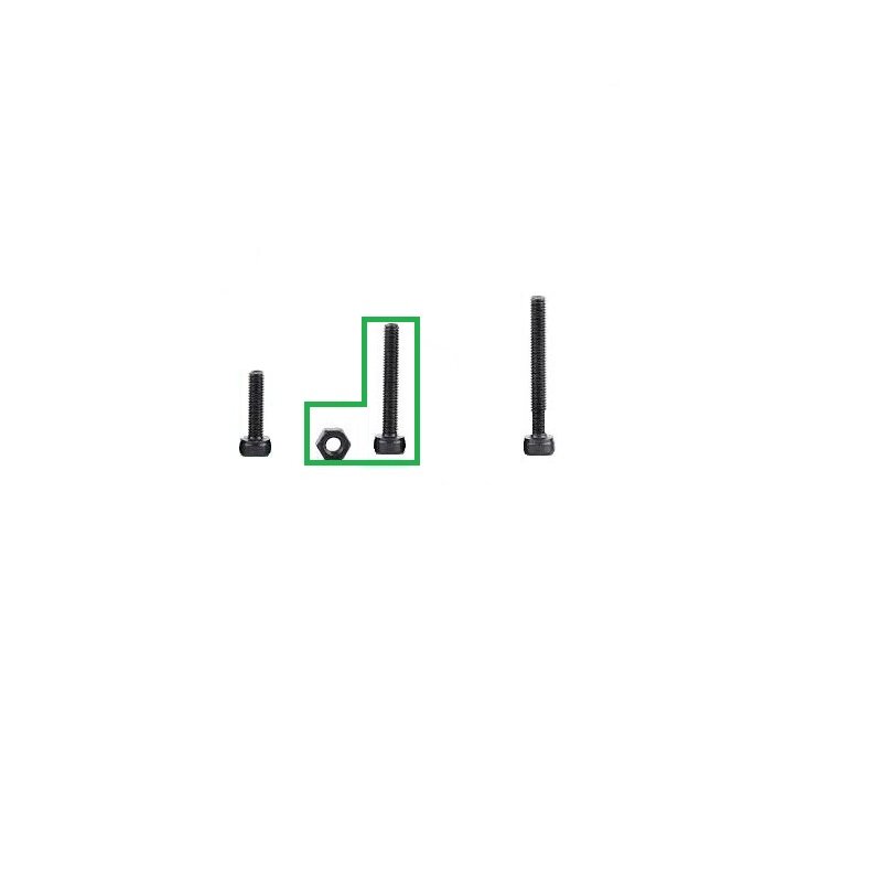
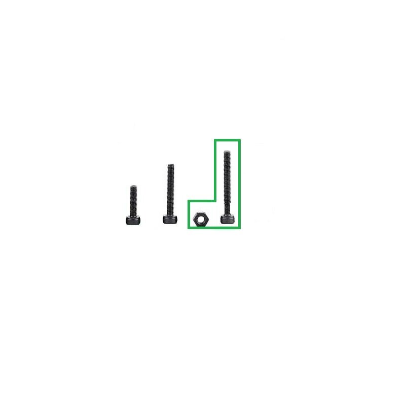
Fasten tight all 4 M3-25 bolts
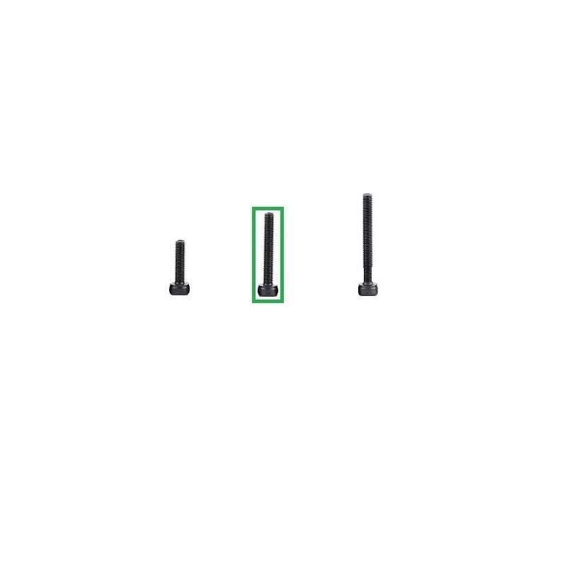
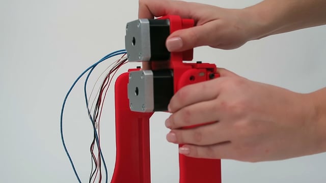
e
Z axis motor
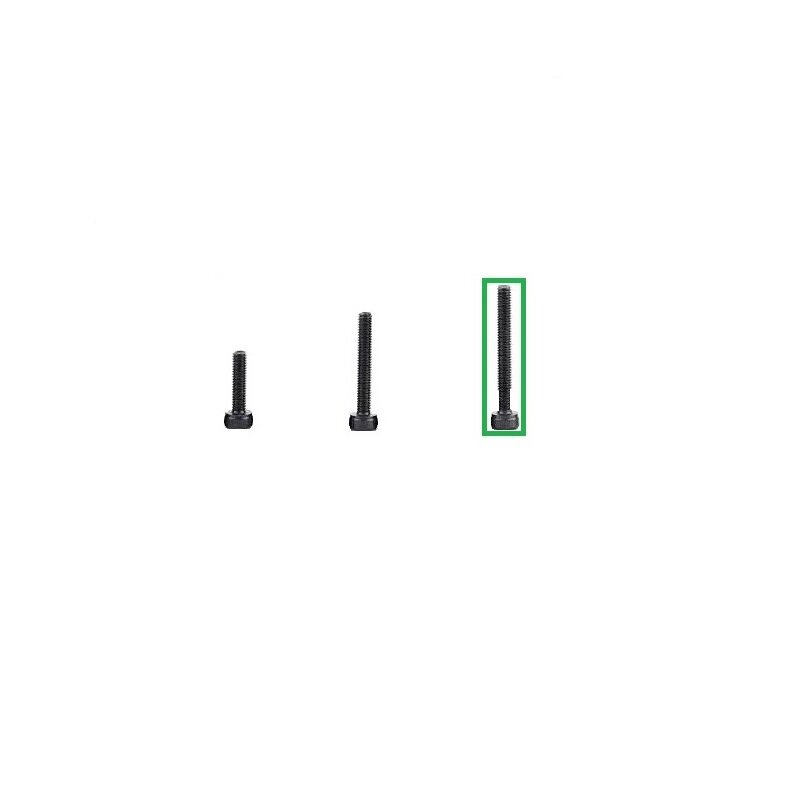
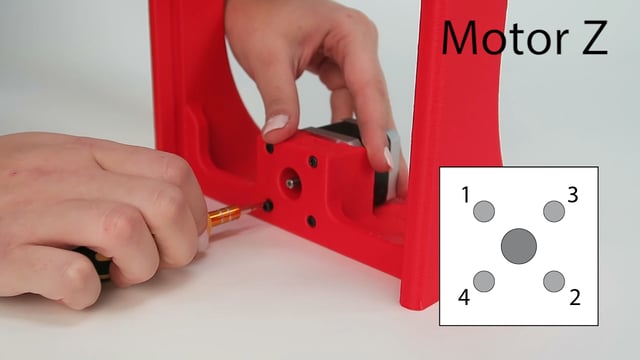
Fasten tight all 4 M3-25 bolts
f
Y axis motor


Fasten tight all 4 M3-25 bolts
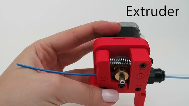
g
Extruder motor

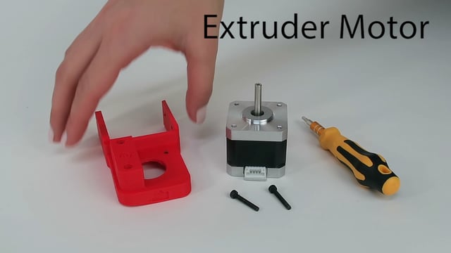
Fasten tight both M3-20 bolts
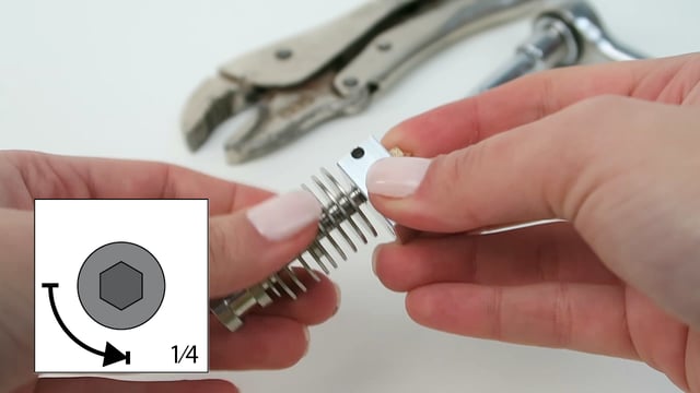
h
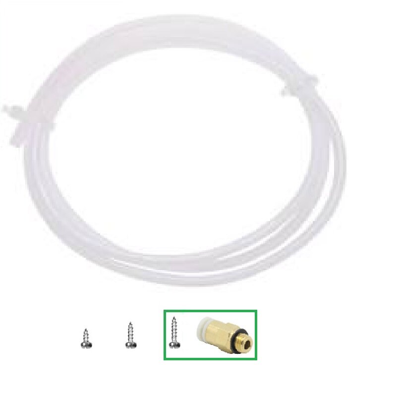
Extruder assembly (PTFE Coupler)
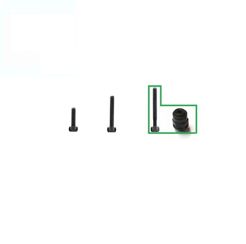
If the hole is small, sand the inner wall then use a wrench to fasten the coupler tight
i
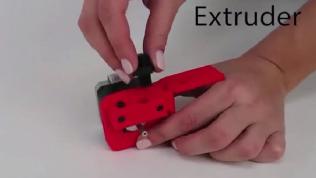
Extruder assembly (handle)
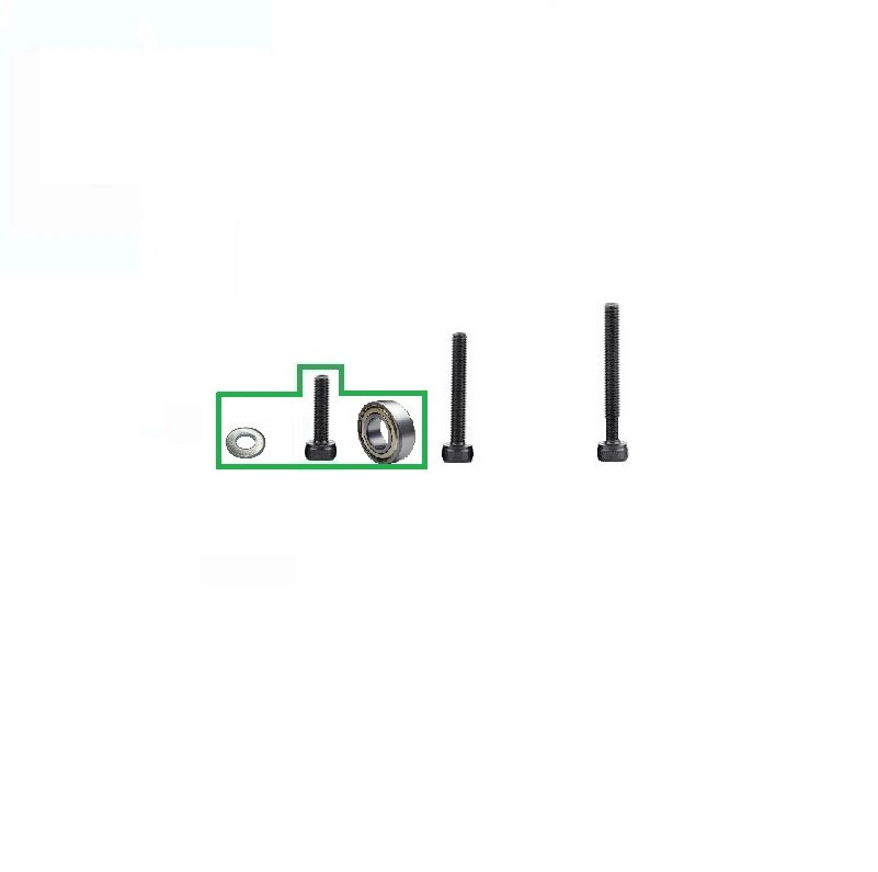
Make sure the ball bearing is moving freely after assembly
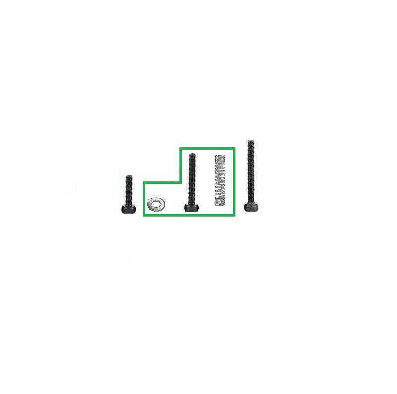
j
Extruder assembly (spring)
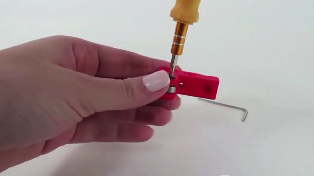
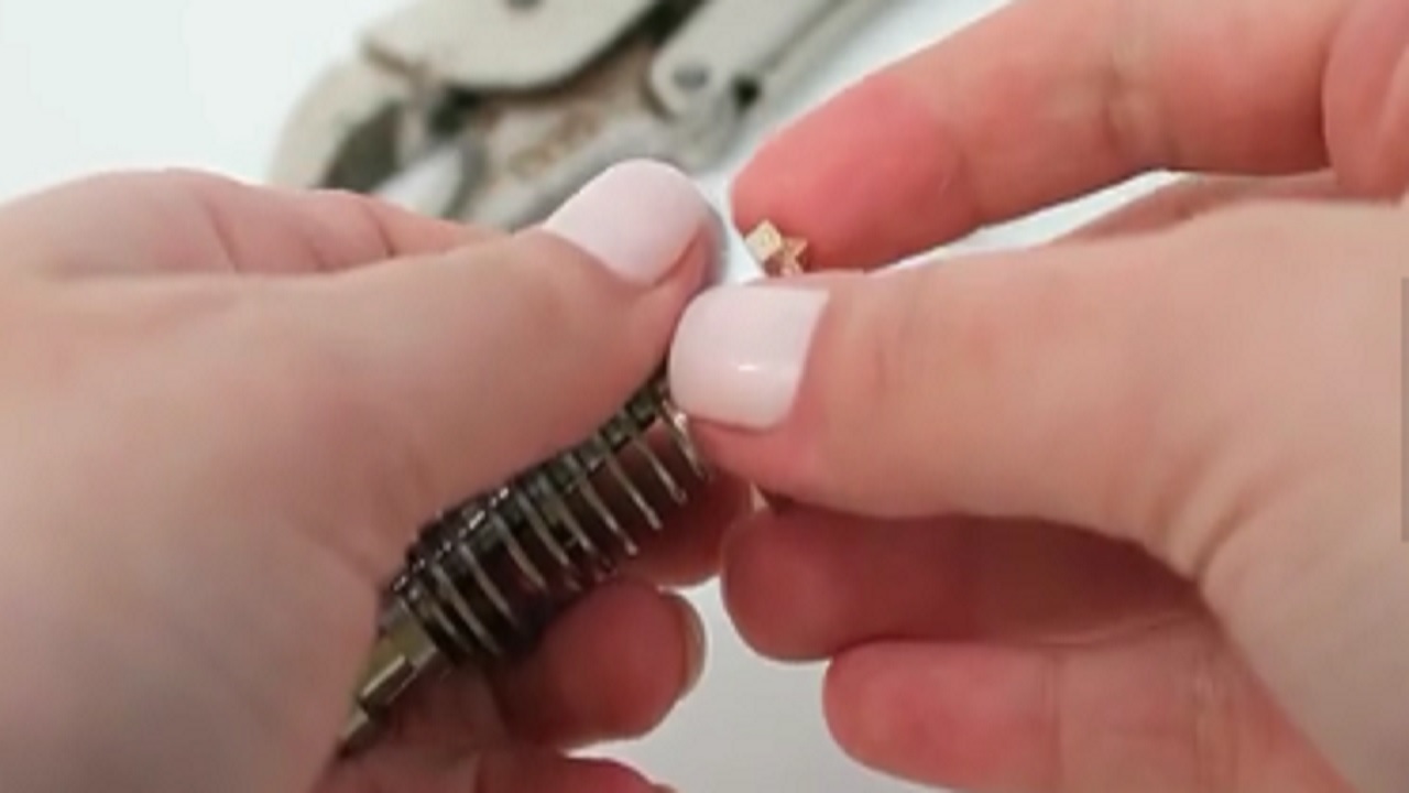
k
Extruder assembly (hobbed gear)
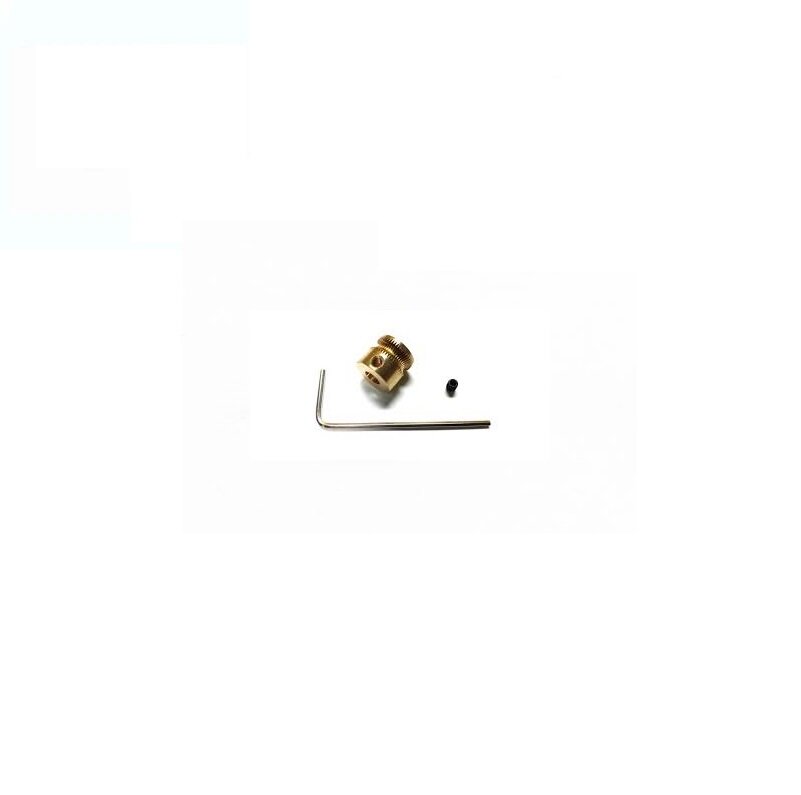
Align the openings with a 6 in. PLA filament
Tighten properly the set screw on the flat side of the shaft
l
X axis Rack preparation
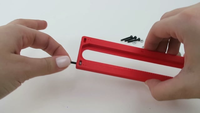
Insert M3 nuts with the flat sides parallel to the openings
Center the M3 nuts with a small Allen key & a test M3 bolt
Spread plasticine to prevent the M3 nuts from falling out
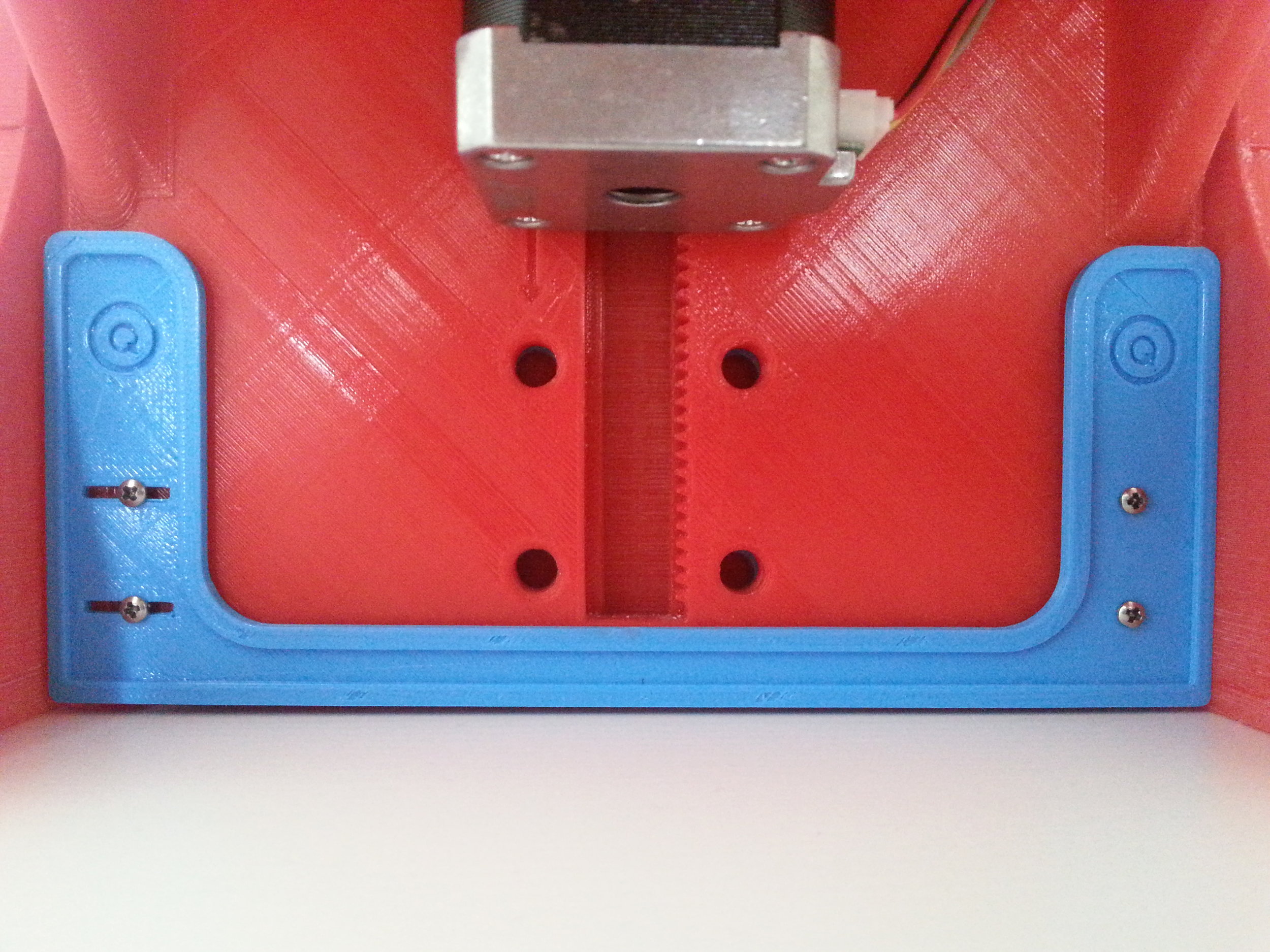
M
x axis rack and pinion
Install the rack with the teeth at the bottom
Add 2 drops of glue inside the opening of the x axis gear
Align the flat side of the motor shaft with the flat side of the gear, hold the backside of the motor and push in the gear
Do not tap on the the motor, it will damage it
Allow the glue to dry for 5 minutes
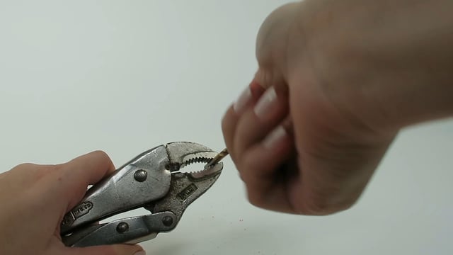
To remove the gear, break off the head with pliers, remove the motor, then cut off the rest with cutters
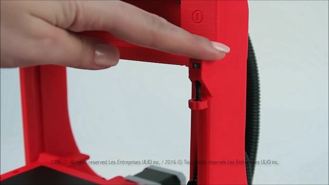
N
x axis rack and pinion adjustment
This step is only required, if you’re having problems moving the X axis rack. Else skip to the next section.
Ease the pressure between the rack & pinion by raising the X axis motor
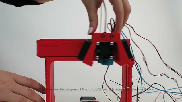
O
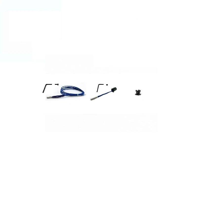
Hotend assembly - part 1
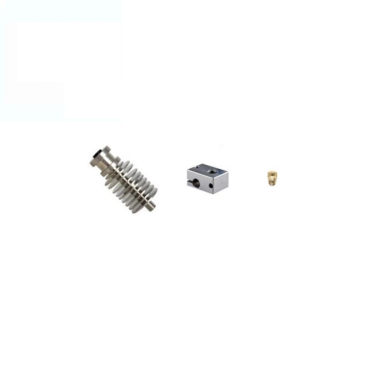
Important notice
At 39 sec. make sure to hold the nozzle with your finger while retightening the heatsink into the heater block
P
Hotend assembly - part 2
Tighten securely the heater cartridge in place (it's normal to see the aluminum block bend a little)
Unlike the heating block, do not over tighten the thermistor screw otherwise you risk permanent damage
Stop tightening as soon as you feel a bit of resistance
Make sure the thermistor does not move
Tie rap the thermistor to the wiring of the heater cartridge
Q
Hotend installation
Unlike what’s shown in the video, turn the hotend so the shorter side of the heater block is facing you
You don’t have to install the M4 nuts if it’s too hard to fasten
R
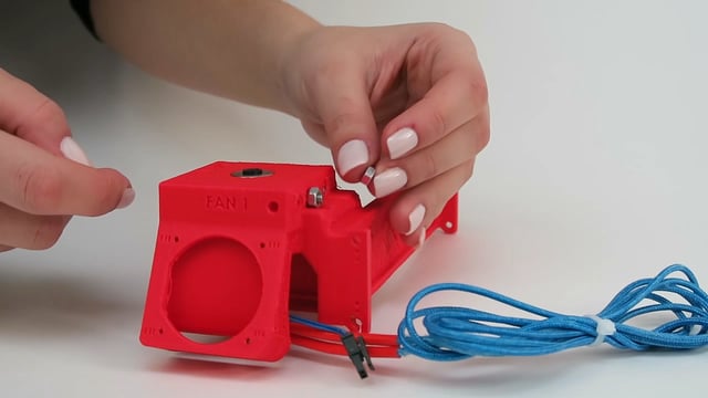
Side cooling fans (FAN1)

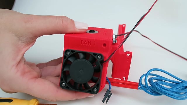
Do not hold the fans with the blades
S
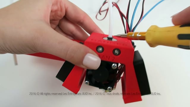
Hotend cooling fan (FAN2)

Do not hold the fans with the blades
The hotend cooling fan (FAN2) might come with long wires
T
Hotend silicone cover
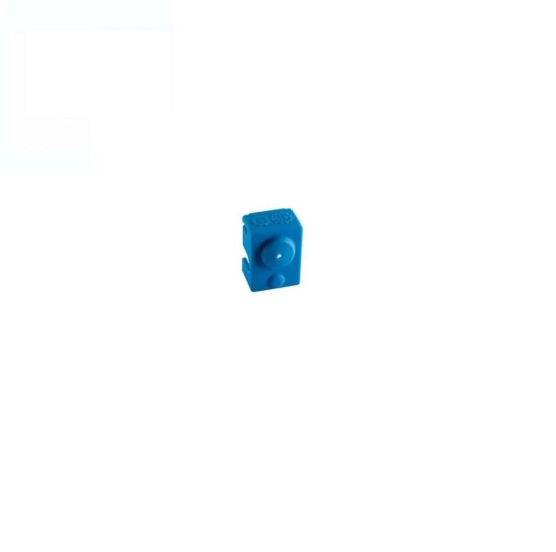

Do not hold the fans with the blades
U
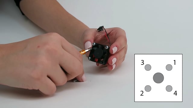
Hotend and faNs wiring
FAN2: The hotend cooling fan might have similar wire connectors to the thermistor (T0)
FAN1: The longer cable connects to the fan on the left while the shorter cable connects to the fan on the right
The attached bundle of wires should not be sticking out or they might restrict movement of the X axis rack
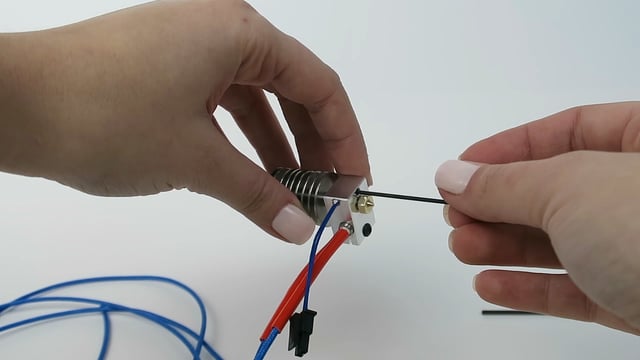
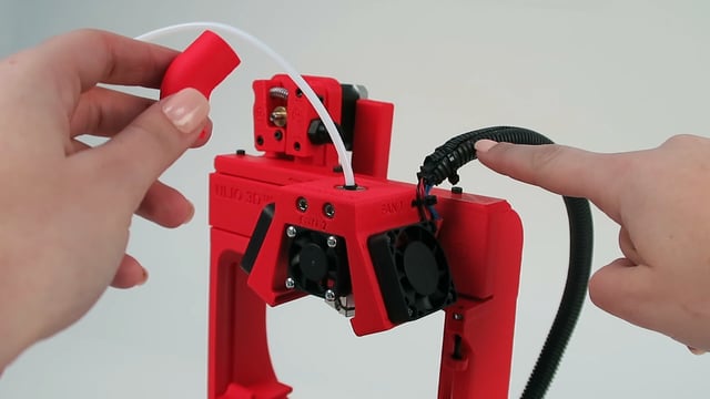
V
Hotend PTFE tubing
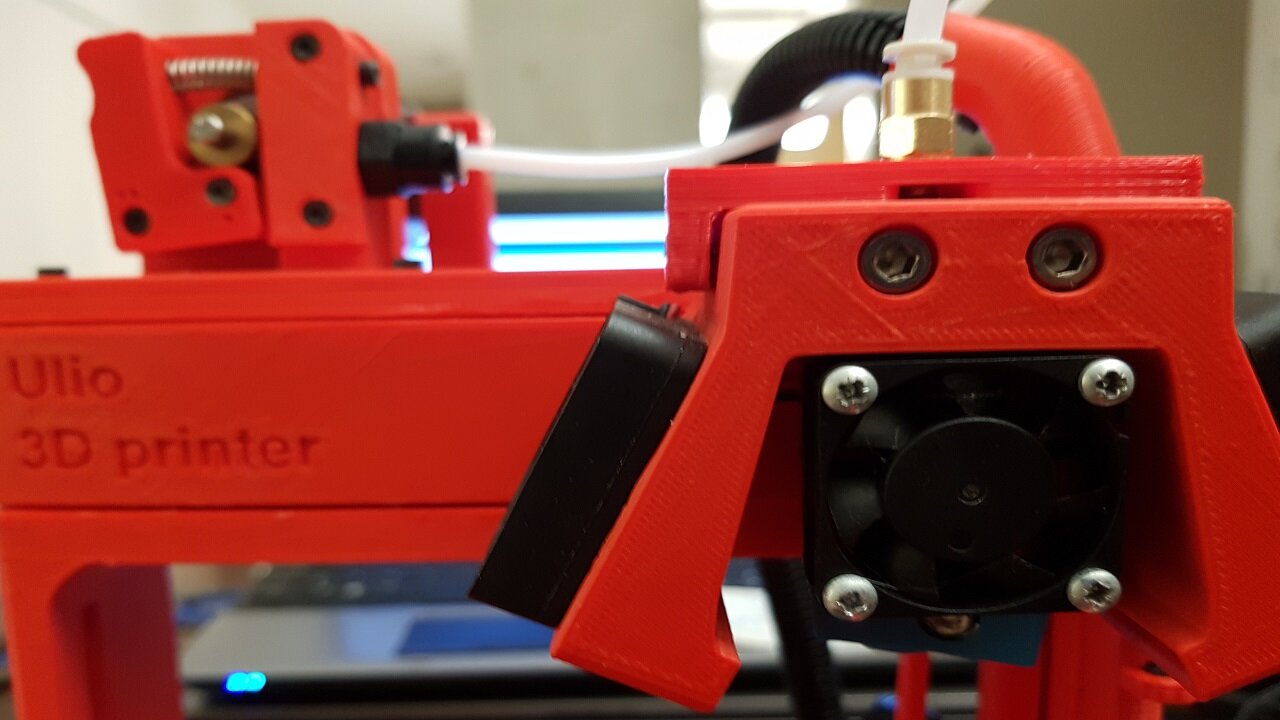
Option 1:
Advanced installation greatly reduces hotend jams
Option 2:
Typical installation, prone to hotend jams
Cut the ends of the PTFE tubing perfectly flat
Insert the PTFE tubing 5 cm into the heatsink
Lock into place the Bowden tube by lifting the black plastic coupler then insert the blue retaining clip
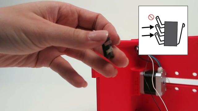
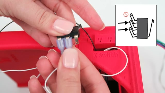
W
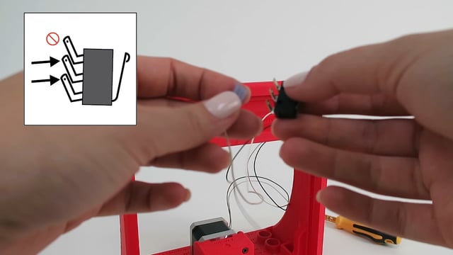
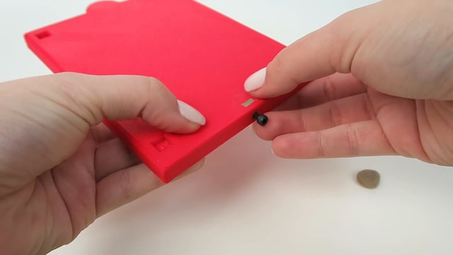
end switch preparation
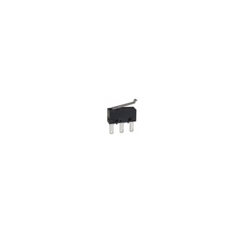
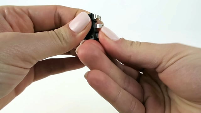
Bend the pins in the right direction
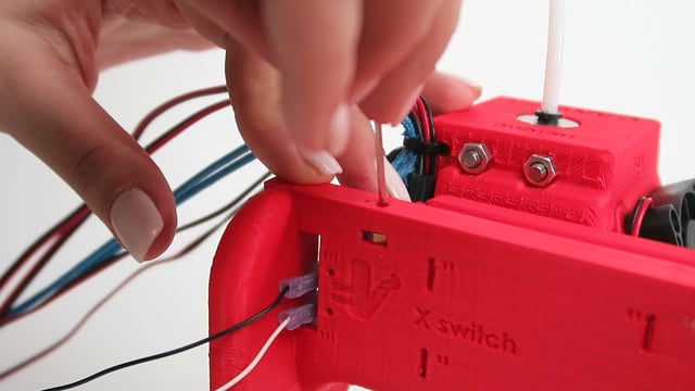
X
X axis end switch

Y
Mounting the hotend
Handle this part gently while installing it on the X axis rack
If it's difficult to screw the M3-12 bolts, do not force!
The nuts are not properly centered
Some plastic strings are still in the openings
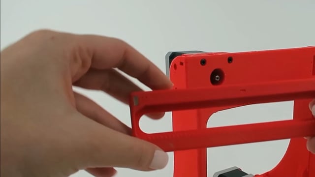
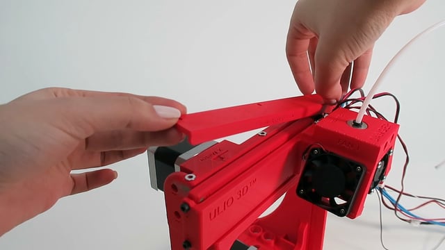
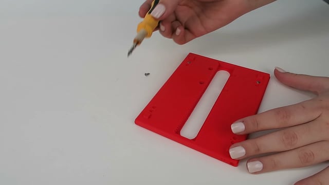
Z
rack holder preparation

Insert the M3 nuts with the sides parallel to the openings
Center the M3 nuts with a small allen key and a bolt
Spread plasticine to prevent the M3 nuts from falling out
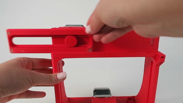
AA
rack holder installation

Install the 3 washers
Push back part I then fasten tight the M3-12 bolts
The X rack should move with ease, if not loosen up a bit the bolts
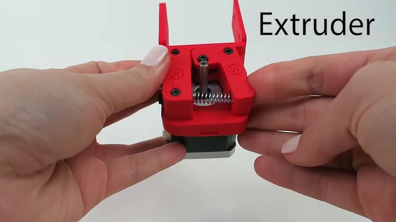
BB
Mounting the extruder
CC
leveling screws on the Y axis rack
Make sure the screws are flush up against the top surface
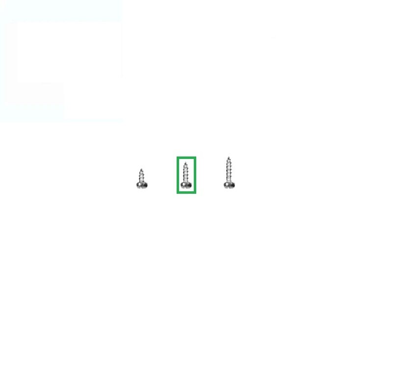
Once installed, the Y rack must close the Y end switch, if not you’ll need to add 1 x Phillips screw 3/8 in. at the tip
DD
Y AXIS RACK and PINION
install the Y axis rack with the teeth facing the same direction as shown in the video
Add 2 drops of glue inside the opening of the y axis gear
Align the flat side of the motor shaft with the flat side of the gear, hold the backside of the motor and push in the gear
Do not tap on the the motor, it will damage it
Allow the glue to dry for 5 minutes
To remove the gear, break off the head with pliers, remove the motor, then cut off the rest with cutters
EE
X, Y, Z and extruder motors wiring
FF
Y axis END SWITCH
GG
Z AXIS END SWITCH

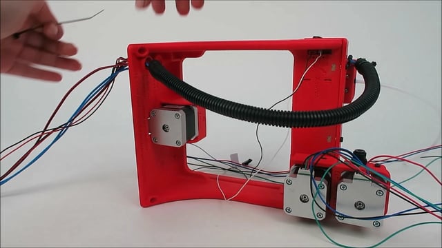
HH
Cable management
Hotend, Fan 1 & 2
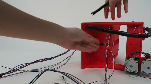
II
Cable management
Y motor, Y and Z end switches

JJ
Cable management
X and Extruder motors, X end switch
Scotch tape and tie raps
KK
Microcontroller connections

Ground yourself before working with electronics
Follow the color code of the motor wiring, otherwise the motors will turn in the wrong direction
Press down tight all the connectors especially the motors
Non polarized connectors (you can reverse the wires)
Thermistor (T0)
X, Y and Z end switches
The heater cartridge (tagged as Extruder)
Polarized connectors (you can’t reverse the wires)
FAN 1 & 2 (red wire must be on the side of the USB)
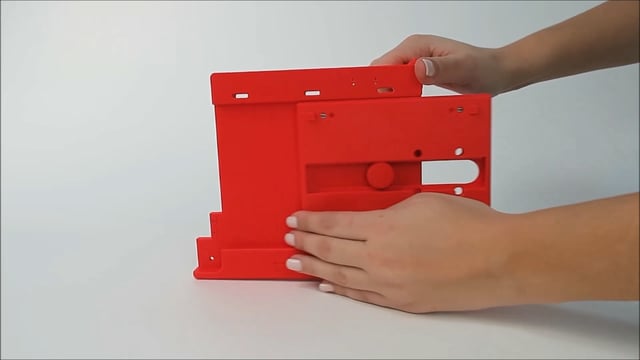
LL
Enclosure preparation
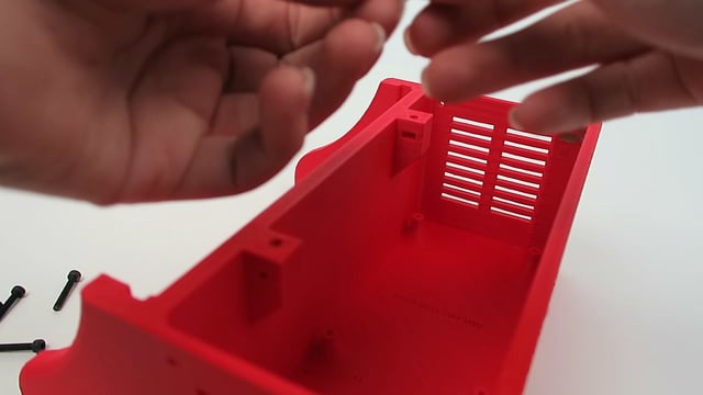
Insert the M3 nuts with the sides parallel to the openings
Center the M3 nuts with a small allen key and a bolt
Spread plasticine to prevent the M3 nuts from falling out
MM
Power wiring and USB panel mount
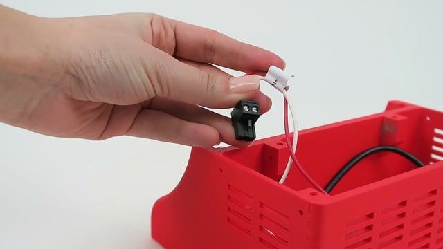
VERY IMPORTANT
Power supply is polarized, you must not reverse the wires
Fasten tight the nut of the DC power jack
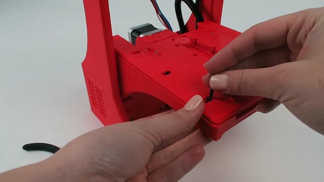
NN
Mounting the microcontroller

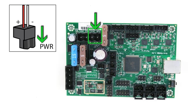
Ground yourself before working with electronics
Power supply is polarized, you must not reverse the wires
The red wire is connected to the pin In+
The white wire is connected to the pin -PWR
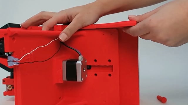
OO
Cable management and printer assembly

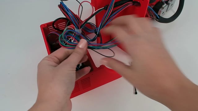
If necessary insert a small Allen key to lock into place the M3 nuts while tightening the bolts
Tie rap both cables (HH & II) so they don't get in the way of the Y axis rack
PP
Z AXIS RACK & PINION
Add 2 drops of glue inside the opening of the z axis gear
Align the flat side of the motor shaft with the flat side of the gear, hold the backside of the motor and push in the gear
Do not tap on the the motor, it will damage it
Allow the glue to dry for 5 minutes
To remove the gear, break off the head with pliers, remove the motor, then cut off the rest with cutters
If the rack and pinion are slipping, minimize their gap
Unscrew the bolts by one turn, push the motor towards the rack, then retighten the bolts
Z axis lateral support
Position and screw the side support
If it’s too long, sand the sides
rr
Y axis side rail
Position the side rail while ensuring the Y rack moves with ease, then fasten the bolts and nuts
SS
Printbed platform preparation

TT
Printbed preparation and assembly
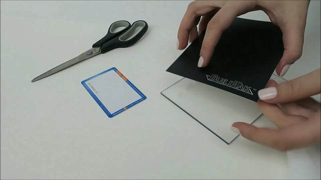
It’s highly unlikely, but If the acrylic sheet is too big simply cut it a local hardware store
When tightening the bolt in place, make sure it does not slip under the acrylic sheet
UU
Printbed LATERAL SUPPORT

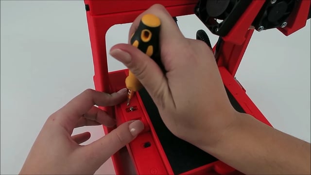
Use a folded paper to adjust the distance between the bracket & the print bed, then tighten the screws
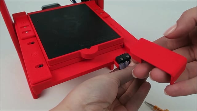
VV
Y AXIS END switch cover

WW
Backside cable covering

XX
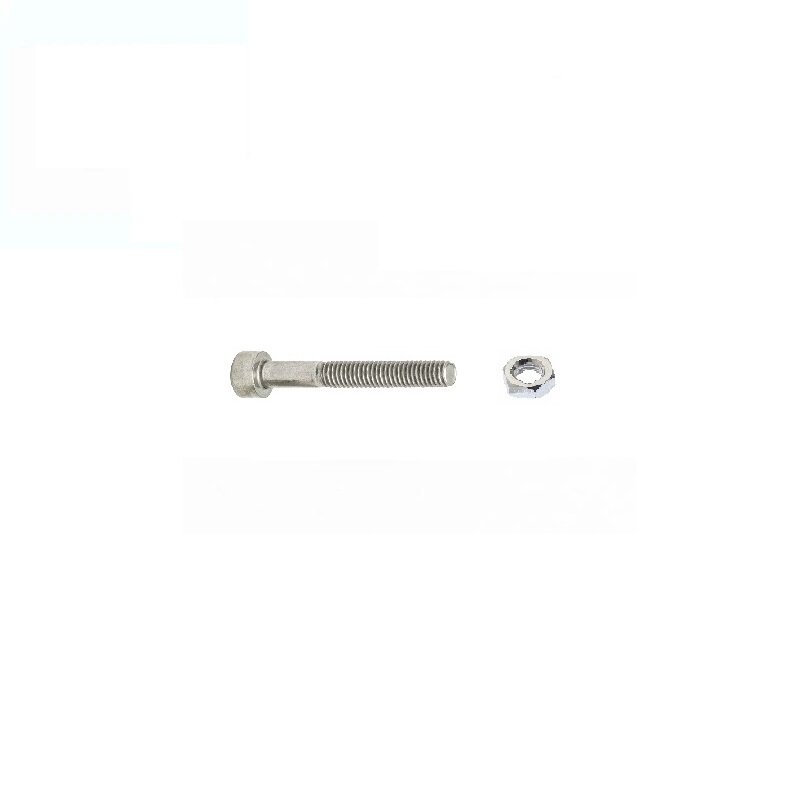
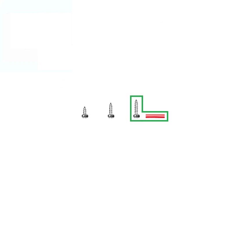
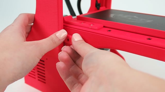
Z axis leveling screw
Before inserting the M3 nut, screw the M3-25 bolt from the top of the opening to widen the plastic hole
Insert the M3 nuts with the sides parallel to the openings
Although it is not shown in the video, you have to glue part T to the head of the M3-25 bolt
YY
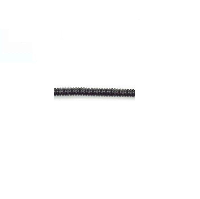
PTFE tubing
ZZ
Z axis additional lateral support
Insert the red tube then install and fasten the screws
Ignore the V design & clear tubing in the video, these were older models but with the same assembly instructions
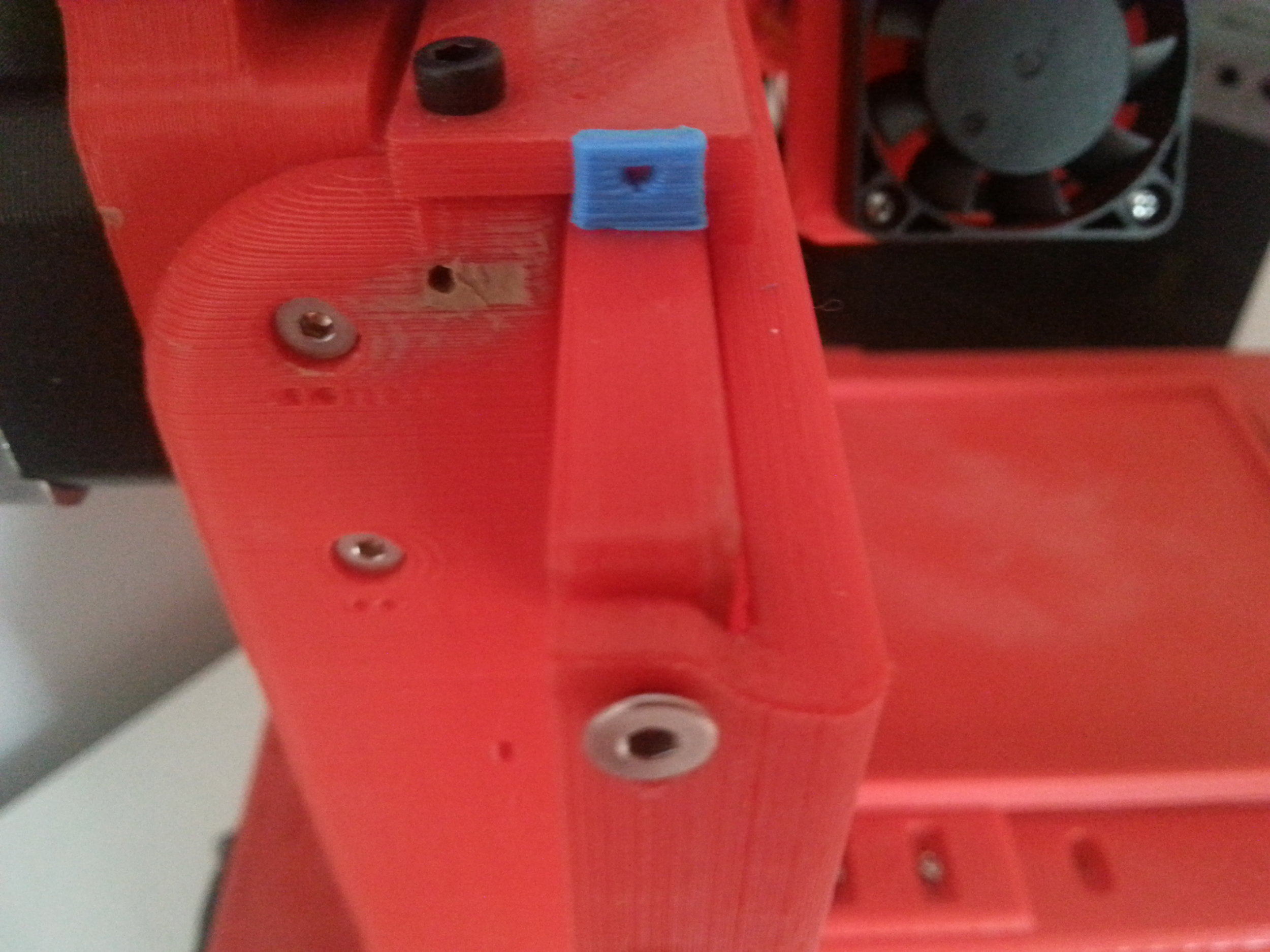
AAA
backside shim on the Z axis

Screw the shim on the backside of part C
Make sure the Z rack still moves with ease, if not reprint a thinner shim
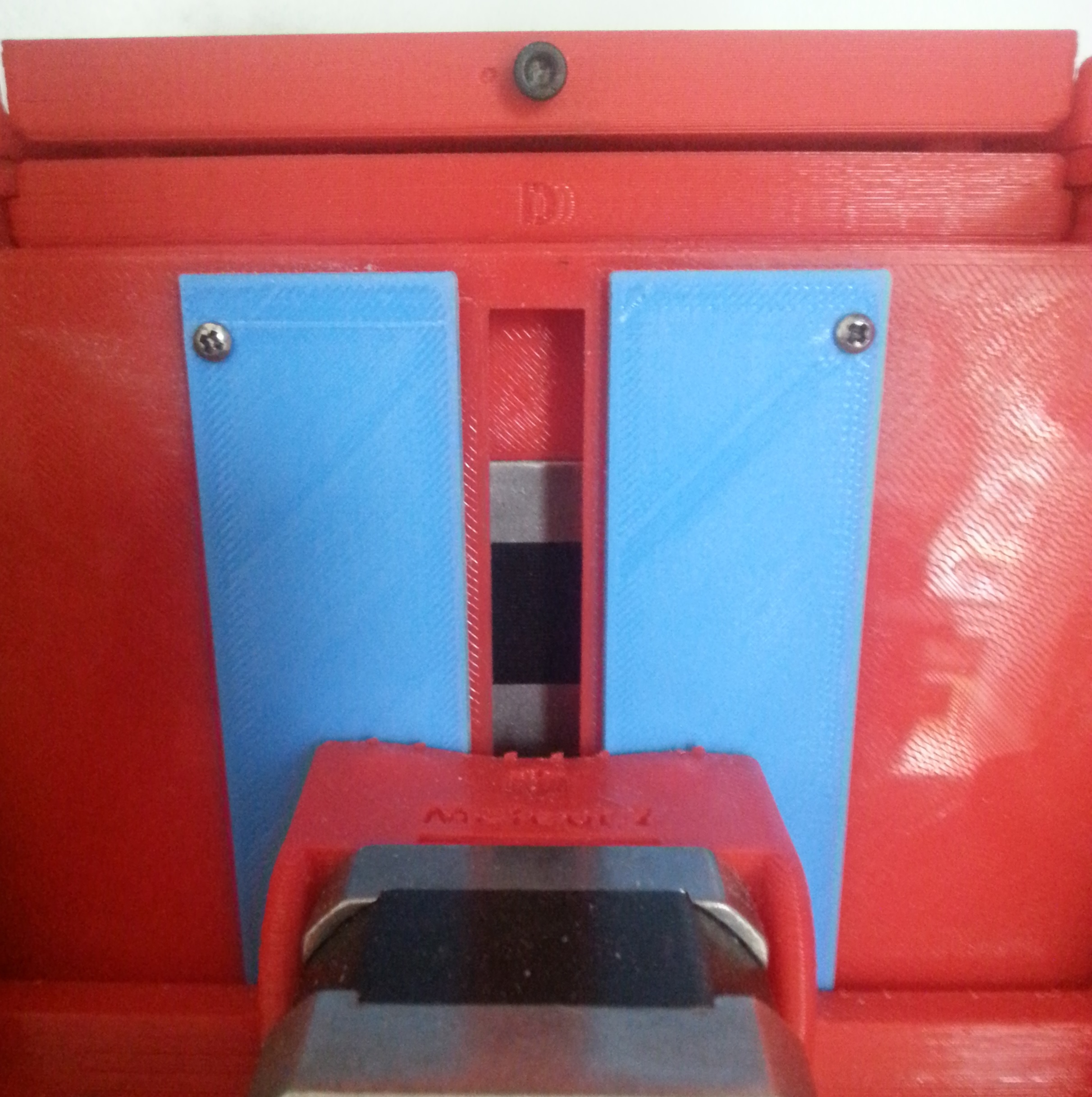
BBB
shim on top of the X axis rack
CCC
LCD enclosure
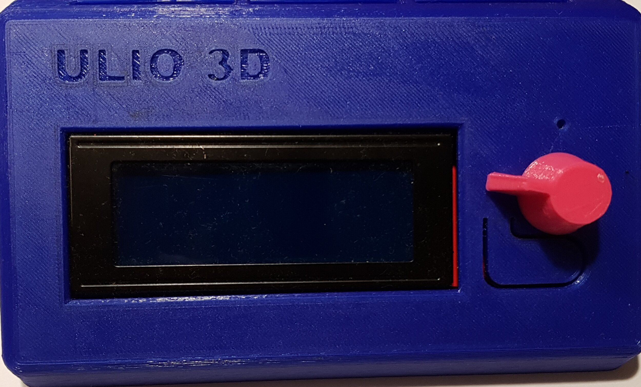

Install the LCD inside the enclosure and fasten the screws
Disassemble the main body of the printer (see section OO)
Connect EXP1 and EXP2 to their respected terminals
Place the LCD cables on the side of the printer
Reassemble the main body of the printer (see section OO)
Fasten the backside of the enclosure
Install the knob
Important notice
DDD
filament Sharpener
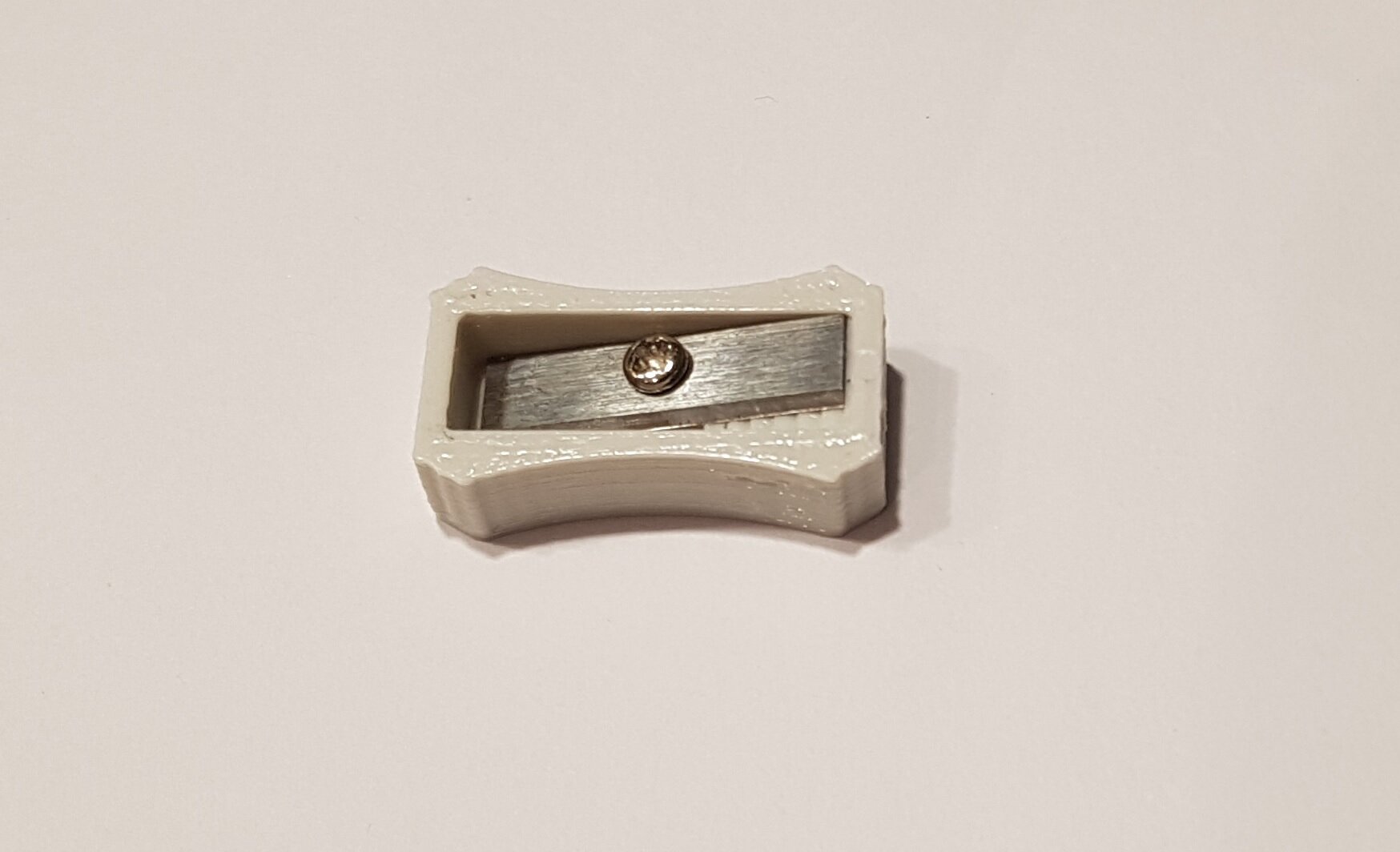
Remove the blade from the pencil sharpener and install it on the 3D printed filament sharpener
very important step - Lubrication
Lubricate all moving parts by:
Adding and rubbing a few drops of good quality sewing machine oil meaning non-staining and non-gumming
Or, adding and rubbing a thin layer of Vaseline